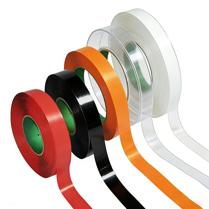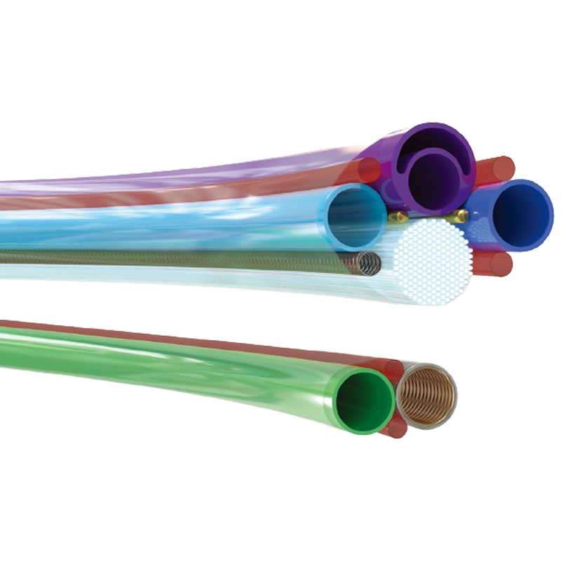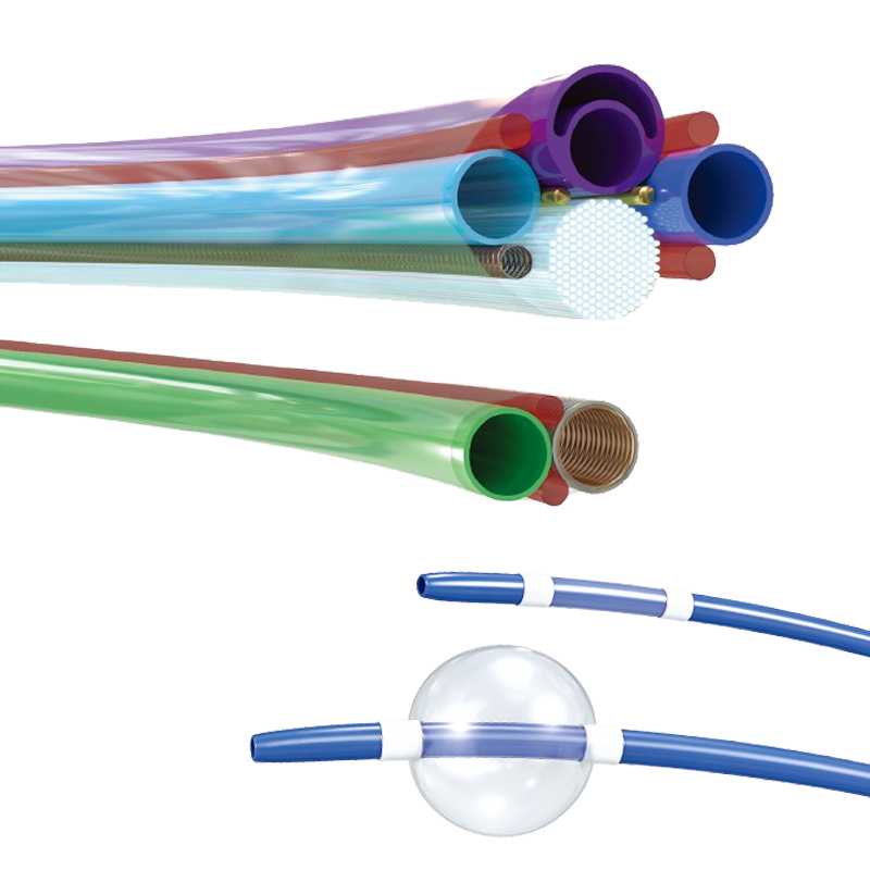

Founded in 2010, FLYPOWER is a high-tech enterprise specializing in the research, development, production, and sales of polymer materials. Leveraging its core technological strengths and starting with heat-shrink materials, the company established its Medical Division in 2018, expanding its business and product portfolio into the fields of medical devices and catheters, with the mission of becoming a globally leading supplier of materials for interventional medical devices.
联系我们 No. 77, Bao Nan Road,Nan Lian Community,Long Gang Street,Long Gang District, Shenzhen, Guangdong,518116,China (+86)755 2917 9250 [email protected]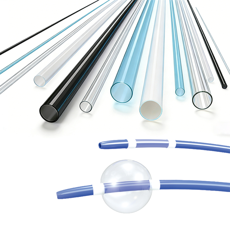
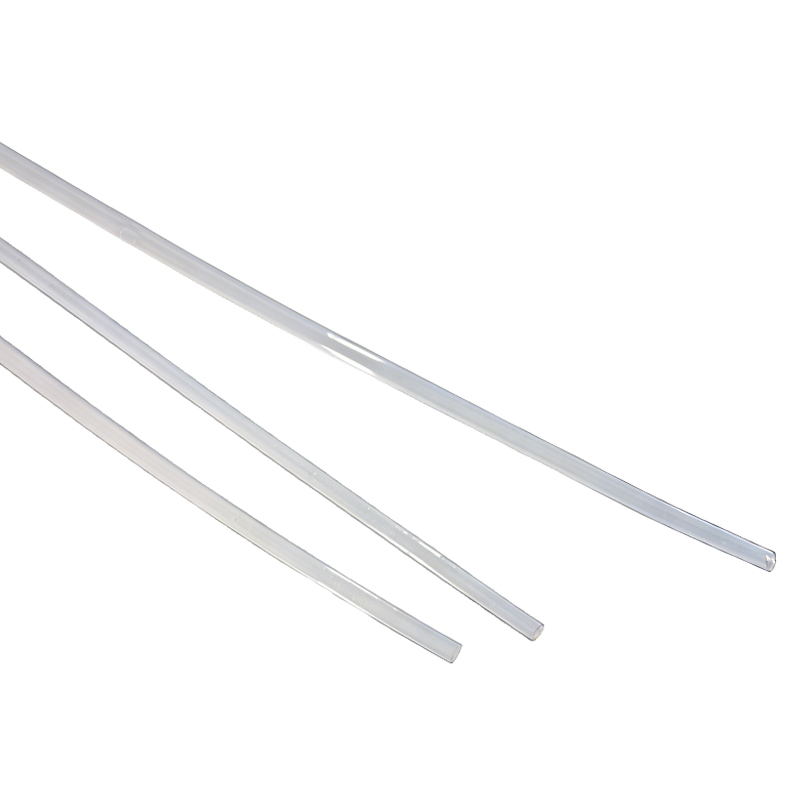
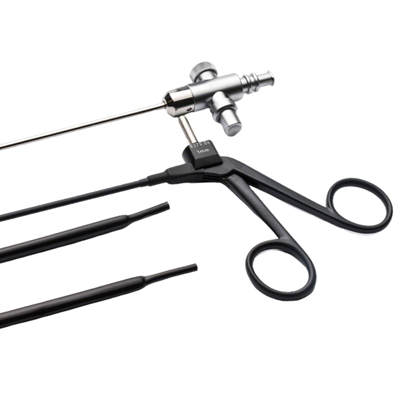
BH-MT-PET-CB heat shrink tubes is made of medical grade Polyethylene terephthalate. Suitable for insulation of medical devices, variable-stiffness catheters, protective covering/coating and bundling, reinforcement, tip forming, tube making and printing, and electrical insulation. Its tough material hardness and ultra-thin wall thickness can fully protect extremely fine products without being affected by thickness.
Thin wall, high tensile strength, high Dielectric strength
Shrink Ratio: 1.3:1 and 1.6:1
Resistant to most chemicals and oils
Compatibility with E-beam, gamma, EtO and autoclave sterilization
Can be printed using conventional techniques
Inner diameter before heat shrinking: 0.3-8mm.
Wall thickness before heat shrinking: 0.0064-0.05mm
Minimum shrink temperature: 85℃
Minimum fully recovery temperature: 190℃
Typical shrinking temperature recommended for most applications: 150°C
Continuous operating temperature: -40˚C~170˚C
Compliant with ISO 10993 and USP Class VI
|
Model Number |
Unit |
Expanded ID |
Expanded WT |
Recovered Max. ID |
Recovered WT |
Standard Length |
||||||||
|
XS |
S |
M |
L |
XL |
XS |
S |
M |
L |
XL |
|||||
|
1.3:1 Shrink ratio |
||||||||||||||
|
MT-PET-CB-1.3X-□-0.30 |
Inch |
0.012±0.001 |
0.0003±0.0001 |
0.0005±0.0001 |
– |
– |
– |
0.01 |
0.0004 |
0.0006 |
– |
– |
– |
50 |
|
mm |
0.30±0.03 |
0.008±0.003 |
0.0127±0.003 |
– |
– |
– |
0.23 |
0.0104 |
0.0165 |
– |
– |
– |
1270 |
|
|
MT-PET-CB-1.3X-□-0.41 |
Inch |
0.016±0.001 |
0.0003±0.0001 |
0.0005±0.0001 |
0.0007±0.0002 |
0.0010±0.0002 |
– |
0.013 |
0.0004 |
0.0006 |
0.001 |
0.0013 |
– |
50 |
|
mm |
0.41±0.03 |
0.008±0.003 |
0.0127±0.003 |
0.019±0.004 |
0.0254±0.005 |
– |
0.32 |
0.0104 |
0.0165 |
0.0247 |
0.033 |
– |
1270 |
|
|
MT-PET-CB-1.3X-□-0.53 |
Inch |
0.021±0.001 |
0.0003±0.0001 |
0.0005±0.0001 |
0.0007±0.0002 |
0.0010±0.0002 |
– |
0.016 |
0.0004 |
0.0006 |
0.001 |
0.0013 |
– |
50 |
|
mm |
0.53±0.03 |
0.008±0.003 |
0.0127±0.003 |
0.019±0.004 |
0.0254±0.005 |
– |
0.41 |
0.0104 |
0.0165 |
0.0247 |
0.033 |
– |
1270 |
|
|
MT-PET-CB-1.3X-□-0.69 |
Inch |
0.027±0.002 |
0.0003±0.0001 |
0.0005±0.0001 |
0.0007±0.0002 |
0.0010±0.0002 |
– |
0.021 |
0.0004 |
0.0006 |
0.001 |
0.0013 |
– |
50 |
|
mm |
0.69±0.05 |
0.008±0.003 |
0.0127±0.003 |
0.019±0.004 |
0.0254±0.005 |
– |
0.53 |
0.0104 |
0.0165 |
0.0247 |
0.033 |
– |
1270 |
|
|
MT-PET-CB-1.3X-□-0.89 |
Inch |
0.035±0.002 |
– |
0.0005±0.0001 |
0.0007±0.0002 |
0.0010±0.0002 |
– |
0.027 |
– |
0.0006 |
0.001 |
0.0013 |
– |
50 |
|
mm |
0.89±0.05 |
– |
0.0127±0.003 |
0.019±0.004 |
0.0254±0.005 |
– |
0.69 |
– |
0.0165 |
0.0247 |
0.033 |
– |
1270 |
|
|
MT-PET-CB-1.3X-□-1.17 |
Inch |
0.046±0.002 |
– |
0.0005±0.0001 |
0.0007±0.0002 |
0.0010±0.0002 |
– |
0.035 |
– |
0.0006 |
0.001 |
0.0013 |
– |
50 |
|
mm |
1.17±0.05 |
– |
0.0127±0.003 |
0.019±0.004 |
0.0254±0.005 |
– |
0.9 |
– |
0.0165 |
0.0247 |
0.033 |
– |
1270 |
|
|
MT-PET-CB-1.3X-□-1.50 |
Inch |
0.059±0.004 |
– |
0.0005±0.0001 |
0.0007±0.0002 |
0.0010±0.0002 |
0.0020±0.0004 |
0.045 |
– |
0.0006 |
0.001 |
0.0013 |
0.0026 |
50 |
|
mm |
1.50±0.10 |
– |
0.0127±0.003 |
0.019±0.004 |
0.0254±0.005 |
0.051±0.01 |
1.15 |
– |
0.0165 |
0.0247 |
0.033 |
0.0663 |
1270 |
|
|
MT-PET-CB-1.3X-□-1.96 |
Inch |
0.077±0.004 |
– |
0.0005±0.0001 |
0.0007±0.0002 |
0.0010±0.0002 |
0.0020±0.0004 |
0.059 |
– |
0.0006 |
0.001 |
0.0013 |
0.0026 |
50 |
|
mm |
1.96±0.10 |
– |
0.0127±0.003 |
0.019±0.004 |
0.0254±0.005 |
0.051±0.01 |
1.51 |
– |
0.0165 |
0.0247 |
0.033 |
0.0663 |
1270 |
|
|
MT-PET-CB-1.3X-□-2.54 |
Inch |
0.100±0.004 |
– |
0.0005±0.0001 |
0.0007±0.0002 |
0.0010±0.0002 |
0.0020±0.0004 |
0.077 |
– |
0.0006 |
0.001 |
0.0013 |
0.0026 |
50 |
|
mm |
2.54±0.10 |
– |
0.0127±0.003 |
0.019±0.004 |
0.0254±0.005 |
0.051±0.01 |
1.95 |
– |
0.0165 |
0.0247 |
0.033 |
0.0663 |
1270 |
|
|
MT-PET-CB-1.3X-□-3.33 |
Inch |
0.131±0.008 |
– |
0.0006±0.0001 |
0.0007±0.0002 |
0.0010±0.0002 |
0.0020±0.0004 |
0.101 |
– |
0.0008 |
0.001 |
0.0013 |
0.0026 |
50 |
|
mm |
3.33±0.20 |
– |
0.0152±0.003 |
0.019±0.004 |
0.0254±0.005 |
0.051±0.01 |
2.56 |
– |
0.0198 |
0.0247 |
0.033 |
0.0663 |
1270 |
|
|
MT-PET-CB-1.3X-□-4.32 |
Inch |
0.170±0.008 |
– |
0.0007±0.0001 |
0.0010±0.0002 |
0.0014±0.0002 |
0.0020±0.0004 |
0.131 |
– |
0.0009 |
0.0013 |
0.0018 |
0.0026 |
50 |
|
mm |
4.32±0.20 |
– |
0.0178±0.003 |
0.026±0.004 |
0.0360±0.005 |
0.051±0.01 |
3.32 |
– |
0.0231 |
0.0338 |
0.0468 |
0.0663 |
1270 |
|
|
MT-PET-CB-1.3X-□-5.61 |
Inch |
0.221±0.011 |
– |
0.0008±0.0001 |
0.0012±0.0002 |
0.0017±0.0002 |
0.0020±0.0004 |
0.17 |
– |
0.001 |
0.0015 |
0.0021 |
0.0026 |
50 |
|
mm |
5.61±0.28 |
– |
0.0203±0.003 |
0.030±0.004 |
0.0420±0.005 |
0.051±0.01 |
4.32 |
– |
0.0264 |
0.039 |
0.0546 |
0.0663 |
1270 |
|
|
MT-PET-CB-1.3X-□-7.29 |
Inch |
0.287±0.015 |
– |
0.0009±0.0001 |
0.0013±0.0002 |
0.0019±0.0002 |
0.0020±0.0004 |
0.221 |
– |
0.0012 |
0.0017 |
0.0024 |
0.0026 |
50 |
|
mm |
7.29±0.38 |
– |
0.0229±0.003 |
0.034±0.004 |
0.0470±0.005 |
0.051±0.01 |
5.61 |
– |
0.0298 |
0.0442 |
0.0611 |
0.0663 |
1270 |
|
|
1.6:1 Shrink ratio |
||||||||||||||
|
MT-PET-CB-1.6X-□-0.30 |
Inch |
0.012±0.001 |
0.0003±0.0001 |
0.0005±0.0001 |
– |
– |
– |
0.007 |
0.0005 |
0.0008 |
– |
– |
– |
50 |
|
mm |
0.30±0.03 |
0.008±0.003 |
0.0127±0.003 |
– |
– |
– |
0.19 |
0.0128 |
0.0203 |
– |
– |
– |
1270 |
|
|
MT-PET-CB-1.6X-□-0.41 |
Inch |
0.016±0.001 |
0.0003±0.0001 |
0.0005±0.0001 |
0.0007±0.0002 |
0.0010±0.0002 |
– |
0.01 |
0.0005 |
0.0008 |
0.0012 |
0.0016 |
– |
50 |
|
mm |
0.41±0.03 |
0.008±0.003 |
0.0127±0.003 |
0.019±0.004 |
0.0254±0.005 |
– |
0.26 |
0.0128 |
0.0203 |
0.0304 |
0.0406 |
– |
1270 |
|
|
MT-PET-CB-1.6X-□-0.53 |
Inch |
0.021±0.001 |
0.0003±0.0001 |
0.0005±0.0001 |
0.0007±0.0002 |
0.0010±0.0002 |
– |
0.013 |
0.0005 |
0.0008 |
0.0012 |
0.0016 |
– |
50 |
|
mm |
0.53±0.03 |
0.008±0.003 |
0.0127±0.003 |
0.019±0.004 |
0.0254±0.005 |
– |
0.33 |
0.0128 |
0.0203 |
0.0304 |
0.0406 |
– |
1270 |
|
|
MT-PET-CB-1.6X-□-0.69 |
Inch |
0.027±0.002 |
0.0003±0.0001 |
0.0005±0.0001 |
0.0007±0.0002 |
0.0010±0.0002 |
– |
0.017 |
0.0005 |
0.0008 |
0.0012 |
0.0016 |
– |
50 |
|
mm |
0.69±0.05 |
0.008±0.003 |
0.0127±0.003 |
0.019±0.004 |
0.0254±0.005 |
– |
0.43 |
0.0128 |
0.0203 |
0.0304 |
0.0406 |
– |
1270 |
|
|
MT-PET-CB-1.6X-□-0.89 |
Inch |
0.035±0.002 |
– |
0.0005±0.0001 |
0.0007±0.0002 |
0.0010±0.0002 |
– |
0.022 |
– |
0.0008 |
0.0012 |
0.0016 |
– |
50 |
|
mm |
0.89±0.05 |
– |
0.0127±0.003 |
0.019±0.004 |
0.0254±0.005 |
– |
0.56 |
– |
0.0203 |
0.0304 |
0.0406 |
– |
1270 |
|
|
MT-PET-CB-1.6X-□-1.17 |
Inch |
0.046±0.002 |
– |
0.0005±0.0001 |
0.0007±0.0002 |
0.0010±0.0002 |
– |
0.029 |
– |
0.0008 |
0.0012 |
0.0016 |
– |
50 |
|
mm |
1.17±0.05 |
– |
0.0127±0.003 |
0.019±0.004 |
0.0254±0.005 |
– |
0.73 |
– |
0.0203 |
0.0304 |
0.0406 |
– |
1270 |
|
|
MT-PET-CB-1.6X-□-1.50 |
Inch |
0.059±0.004 |
– |
0.0005±0.0001 |
0.0007±0.0002 |
0.0010±0.0002 |
0.0020±0.0004 |
0.037 |
– |
0.0008 |
0.0012 |
0.0016 |
0.0032 |
50 |
|
mm |
1.50±0.10 |
– |
0.0127±0.003 |
0.019±0.004 |
0.0254±0.005 |
0.051±0.01 |
0.94 |
– |
0.0203 |
0.0304 |
0.0406 |
0.0816 |
1270 |
|
|
MT-PET-CB-1.6X-□-1.96 |
Inch |
0.077±0.004 |
– |
0.0005±0.0001 |
0.0007±0.0002 |
0.0010±0.0002 |
0.0020±0.0004 |
0.048 |
– |
0.0008 |
0.0012 |
0.0016 |
0.0032 |
50 |
|
mm |
1.96±0.10 |
– |
0.0127±0.003 |
0.019±0.004 |
0.0254±0.005 |
0.051±0.01 |
1.23 |
– |
0.0203 |
0.0304 |
0.0406 |
0.0816 |
1270 |
|
|
MT-PET-CB-1.6X-□-2.54 |
Inch |
0.100±0.004 |
– |
0.0005±0.0001 |
0.0007±0.0002 |
0.0010±0.0002 |
0.0020±0.0004 |
0.063 |
– |
0.0008 |
0.0012 |
0.0016 |
0.0032 |
50 |
|
mm |
2.54±0.10 |
– |
0.0127±0.003 |
0.019±0.004 |
0.0254±0.005 |
0.051±0.01 |
1.59 |
– |
0.0203 |
0.0304 |
0.0406 |
0.0816 |
1270 |
|
|
MT-PET-CB-1.6X-□-3.33 |
Inch |
0.131±0.008 |
– |
0.0006±0.0001 |
0.0007±0.0002 |
0.0010±0.0002 |
0.0020±0.0004 |
0.082 |
– |
0.001 |
0.0012 |
0.0016 |
0.0032 |
50 |
|
mm |
3.33±0.20 |
– |
0.0152±0.003 |
0.019±0.004 |
0.0254±0.005 |
0.051±0.01 |
2.08 |
– |
0.0243 |
0.0304 |
0.0406 |
0.0816 |
1270 |
|
|
MT-PET-CB-1.6X-□-4.32 |
Inch |
0.170±0.008 |
– |
0.0007±0.0001 |
0.0010±0.0002 |
0.0014±0.0002 |
0.0020±0.0004 |
0.106 |
– |
0.0011 |
0.0016 |
0.0023 |
0.0032 |
50 |
|
mm |
4.32±0.20 |
– |
0.0178±0.003 |
0.026±0.004 |
0.0360±0.005 |
0.051±0.01 |
2.7 |
– |
0.0285 |
0.0416 |
0.0576 |
0.0816 |
1270 |
|
|
MT-PET-CB-1.6X-□-5.61 |
Inch |
0.221±0.011 |
– |
0.0008±0.0001 |
0.0012±0.0002 |
0.0017±0.0002 |
0.0020±0.0004 |
0.138 |
– |
0.0013 |
0.0019 |
0.0026 |
0.0032 |
50 |
|
mm |
5.61±0.28 |
– |
0.0203±0.003 |
0.030±0.004 |
0.0420±0.005 |
0.051±0.01 |
3.51 |
– |
0.0325 |
0.048 |
0.0672 |
0.0816 |
1270 |
|
|
MT-PET-CB-1.6X-□-7.29 |
Inch |
0.287±0.015 |
– |
0.0009±0.0001 |
0.0013±0.0002 |
0.0019±0.0002 |
0.0020±0.0004 |
0.18 |
– |
0.0014 |
0.0021 |
0.003 |
0.0032 |
50 |
|
mm |
7.29±0.38 |
– |
0.0229±0.003 |
0.034±0.004 |
0.0470±0.005 |
0.051±0.01 |
4.56 |
– |
0.0366 |
0.0544 |
0.0752 |
0.0816 |
1270 |
|
* The “□” of product model BH-MT-PET-CB corresponds to the wall thickness specifications with numbers XS, S, M, L, and XL indicating different thicknesses.
* Customized dimensions and heat shrink ratio for your special applications on request.
Cross Reference :
Nordson ultra thin wall PET heat shrink tubing, Zeus Sub-Lite-Wall PET heat shrink tubing
|
Property |
Unit |
Performance |
|
Longitudinal change |
% |
-50% ~ -30% |
|
Tensile strength |
MPa |
≥10 (or>20,000 PSI) |
|
Break elongation |
% |
≥62% |
|
Dielectric strength |
KV/mm |
≥15 |
|
Dielectric strength rating |
V/mil |
>4,000 (60Hz) |
|
Dielectric constant |
ε |
3.3 |
|
volume resistivity |
Ω·cm |
≥1018 |
|
Melting point |
°C |
235°C |