|
ITEM
|
INCH
|
MM
|
|
INSIDE DIAMETER (ID )
|
0.01 – 0.11
|
0.30 – 2.79
|
|
ID TOLERANCE
|
± 0.001 – 0.003
|
± 0.025 – 0.076
|
|
NOMINAL WALL THICKNESS
|
0.0004 – 0.0008
|
0.01 – 0.02
|
|
WALL TOLERANCE
|
± 0.0002 – 0.00025
|
± 0.005 – 0.00635
|
|
CUT LENGTH
|
39-78
|
1,000-2,000
|
|
Property
|
Specification Requirement
|
Test Method
|
Typical Value
|
|
Etching Angle
|
<70°
|
–
|
60°
|
|
Flammability
|
V0
|
UL94
|
V0
|
|
Chemical Resistance
|
excellent
|
–
|
excellent
|
|
Heat shock
|
No cracking
|
ASTM D2671
(400˚C/4 hrs)
|
No cracking
|
|
Low temperature flexibility
|
No cracking
|
ASTM D2671
(-65˚C/4 hrs)
|
No cracking
|
|
No heavy metals contained
|
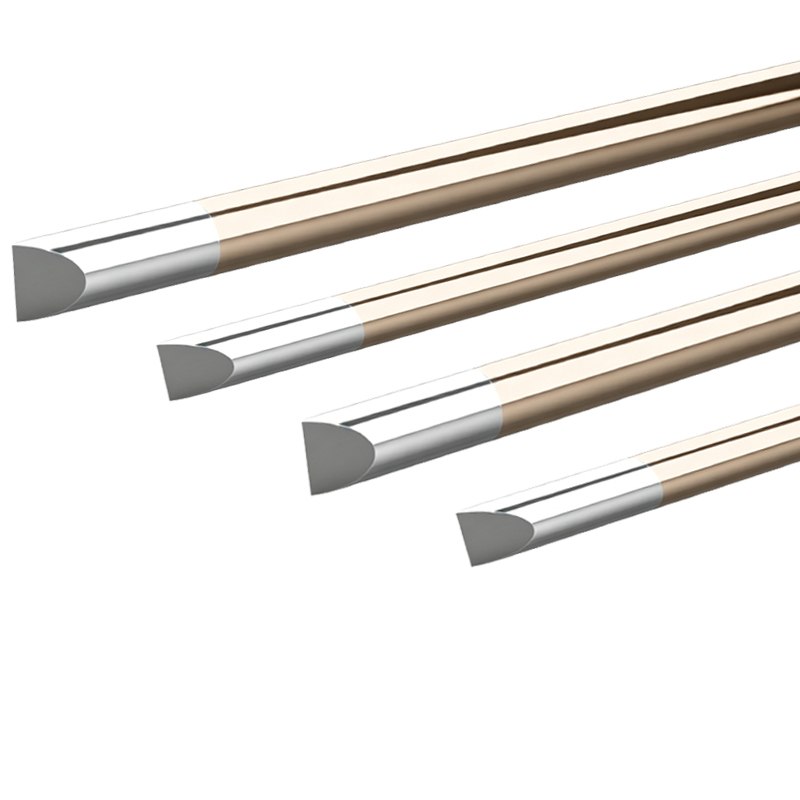
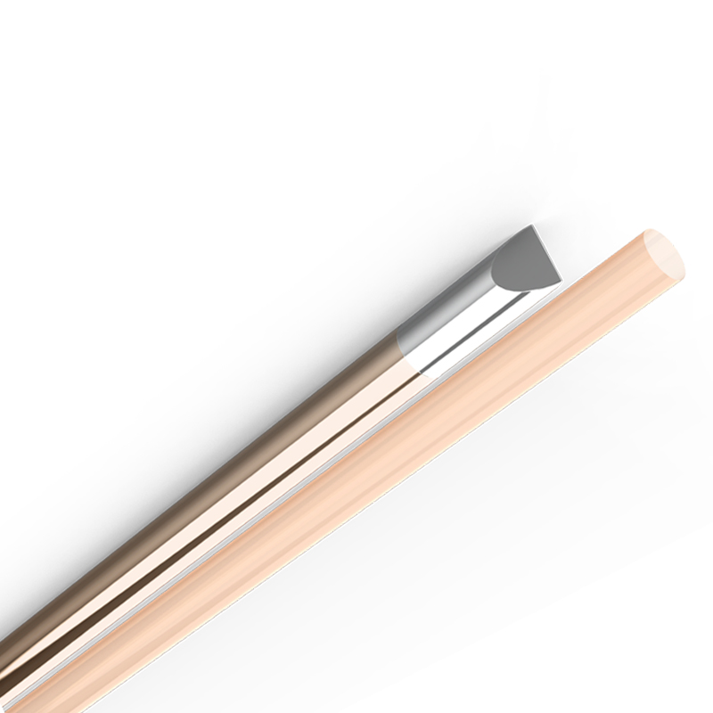
Q1. What is a medical grade OTW etched PTFE liner with mandrel?
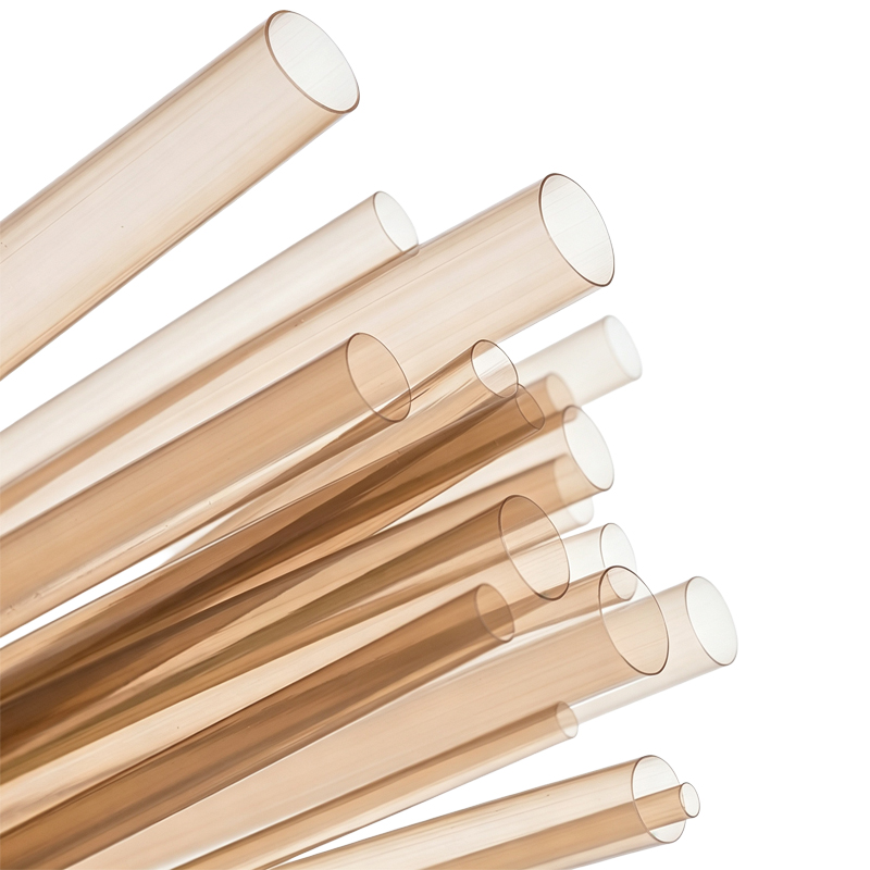
A1. An OTW (over-the-wire) etched PTFE liner is a thin-walled polytetrafluoroethylene tube produced by paste extrusion over a precision mandrel, with the outer surface chemically etched (typically with sodium naphthalenide solution) to render it bondable. The mandrel remains in place during extrusion and sintering to guarantee tight ID control and concentricity — critical for OTW catheter platforms where a guidewire passes through the working lumen. The inner surface retains PTFE’s native ultra-low friction (coefficient ~0.04–0.10), while the etched outer surface accepts adhesives and thermal bonding to Pebax, nylon, TPU, or braided jacket structures. In catheter construction, engineers describe this as the foundational layer of a multilayer shaft: an outer Pebax jacket encapsulated over a surface-etched PTFE liner to achieve low friction inside.
Q2. Why is PTFE still the go-to liner material for interventional catheters?
A2. Engineers on r/MedicalDevices consistently describe PTFE as having “earned its place as a gold standard” for tortuous-path, demanding catheter applications. Its combination of ultra-low friction, chemical inertness, dimensional stability (moisture absorption <0.01%), and proven blood-contact history dating to the 1950s remains unmatched for guidewire passage and implant delivery. For microcatheters and stent delivery systems navigating neurovascular or peripheral tortuosity, the lubricity of a PTFE-lined lumen directly translates to lower procedural force and reduced vessel trauma risk.
Q3. What is the difference between OTW mandrel extrusion and free extrusion for PTFE liners?
A3. Both are paste-extrusion routes — PTFE cannot be melt-extruded like Pebax or nylon due to its extremely high melt viscosity. In OTW mandrel extrusion, the PTFE paste is extruded over a precision wire or pin mandrel and sintered with the mandrel in place. This delivers superior ID tolerance, wall concentricity, and surface finish on the luminal side — essential for OTW platforms where the liner ID must closely match the guidewire. Free extrusion produces the tube unsupported; it suits high-volume production of longer lengths and can enhance axial strength through controlled fibril orientation, but the ID is governed by the assembled construction rather than the liner alone. For microcatheters and delivery systems where lumen precision is critical, mandrel-extruded liners are the standard choice.
Q4. How thin can the wall be, and what tolerances are achievable?
A4. Industry literature and supplier data report paste-extruded PTFE liner walls down to approximately 0.0005″ (12.7 µm) with tolerances on the order of ±0.0003″, and specialized processes can achieve walls down to ~0.0003″ (7.6 µm). For mandrel-extruded OTW liners, typical ID tolerances are held to ±0.0005″ or tighter, with wall concentricity critical for uniform reflow bonding. In finished multilayer catheter shafts, the assembled lumen tolerance is typically ±0.001″, and OD tolerance ±0.002″–±0.003″ depending on jacket and braid configuration. Because PTFE absorbs essentially no moisture, these dimensions remain stable through manufacturing, storage, and use — a key advantage over nylon, which absorbs 0.6–1.0% moisture and can drift in humid environments.
Q5. Why must PTFE be etched before bonding, and how does sodium etching work?
A5. PTFE’s extremely low surface energy (~18 dynes/cm) — the same property that gives it lubricity — makes it essentially non-stick. Adhesives and molten jacket polymers (Pebax, nylon, TPU) will not wet or bond to untreated PTFE. Engineers on Reddit consistently flag PTFE bonding as the #1 processing challenge with this material. Sodium etching (typically sodium naphthalenide solution) removes fluorine atoms from the outer surface and introduces oxygen-containing functional groups, raising surface energy above 50 dynes/cm and creating a microscopically rough surface for mechanical interlock. This is the standard pretreatment before jacketing. Note that etching is applied to the outer surface only; the inner luminal surface remains virgin PTFE.
Q6. What bonding methods work with an etched OTW PTFE liner?
A6. Two mainstream approaches are used: (1) Direct bonding to the etched outer surface via adhesive lamination or thermal reflow — the etched surface accepts adhesives and improves mechanical interlock with the jacket during reflow. (2) Tie-layer technology — a thin thermoplastic elastomer layer (e.g., modified Pebax or polyurethane) is applied to the PTFE outer surface; the tie layer fusion-bonds to PTFE under heat and pressure, and its outer surface bonds readily to the jacket. Tie layers are particularly valuable for ultra-thin-wall constructions where the etched surface alone may not provide sufficient bonding area. Choice depends on jacket material, reflow process, and whether the device will see flex fatigue.
Q7. How is etch quality verified, and what should I specify to my supplier?
A7. Standard verification includes: (1) contact-angle measurement on the etched surface — a properly etched PTFE surface shows a water contact angle below 70° (typically ~60°); (2) dyne-level or surface-energy testing to confirm >50 dynes/cm activation; (3) visual inspection for uniform brownish tint (a normal indicator of sodium etching; absence of tint suggests under-etching, dark discoloration suggests over-etching); (4) peel-strength testing of bonded samples per lot. Etch consistency between batches is a common supplier-quality discussion point among engineers, so specifying contact angle and peel strength as lot-release criteria is recommended.
Q8. How and when is the mandrel removed after extrusion and sintering?
A8. In OTW mandrel extrusion, the mandrel is removed after sintering through a combination of mechanical pulling and, for long or thin-wall sections, hydraulic or pneumatic assistance. The mandrel surface is typically polished and may be coated with a release agent to prevent PTFE adhesion during sintering. Removal force must be carefully controlled — excessive force can ovalize the lumen or induce micro-cracks in the thin wall. Some processes use soluble or collapsible mandrels for complex geometries. The key process window is controlled cooling after sintering: PTFE contracts more than the mandrel material, so proper thermal management ensures clean release without dimensional distortion.
Q9. Does mandrel removal damage the etched surface or affect bonding?
A9. No — etching is performed after extrusion, sintering, and mandrel removal. The sequence is: paste extrusion over mandrel → sintering → mandrel removal → surface etching → cleaning/rinsing → drying → inspection → packaging. This ensures the etched surface is fresh and uncontaminated at the point of bonding. Handling after etching requires care: the etched surface is activated and should be bonded or protected promptly, as surface energy can degrade with prolonged exposure to air, moisture, or contamination.
Q10. Which sterilization methods are compatible with etched OTW PTFE liners?
A10. PTFE is among the most sterilization-compatible catheter polymers. It tolerates ethylene oxide (EtO), steam autoclave (121–134°C), gamma irradiation, e-beam, and vaporized hydrogen peroxide (VHP) without significant degradation — a key advantage over nylon and Pebax, which degrade under gamma/e-beam and absorb moisture during autoclaving. This makes PTFE-lined catheters suitable for single-use devices sterilized by EtO or gamma, and for reusable devices requiring repeated autoclave cycles. Always verify the full assembled device (liner + jacket + adhesive) through the chosen sterilization cycle, since the jacket or bond line is usually the limiting factor, not the PTFE.
Q11. Is sodium-etched PTFE biocompatible for blood-contacting applications?
A11. Yes. Medical-grade PTFE resin is a well-established blood-contacting material with a clinical history dating to the 1950s. It is non-thrombogenic relative to most polymers, chemically inert, and dimensionally stable. Device-level biocompatibility evaluation per ISO 10993-1 (cytotoxicity, sensitization, irritation, hemocompatibility as applicable) is required for the finished device — material-level compliance (e.g., USP Class VI resin) does not substitute for device-level testing. The sodium etching process is applied to the outer surface only and is followed by thorough rinsing and cleaning; residual etchant is removed to non-detectable levels. The inner luminal surface remains virgin, un-etched PTFE throughout.
Q12. Which catheter applications are best suited for OTW etched PTFE liners?
A12. OTW etched PTFE liners are the default choice where guidewire lubricity and lumen precision are critical: guide catheters, diagnostic angiographic catheters, neurovascular microcatheters, steerable/deflectable catheters, introducer sheaths, and stent/balloon delivery systems. For stent delivery systems specifically, the combination of low-friction inner lumen and precise ID control ensures smooth stent deployment without catching or uneven expansion. For larger-diameter peripheral and urological devices where extreme miniaturization matters less, Pebax, nylon, or FEP liners may be more cost-effective; PTFE is sometimes reserved for distal tip segments in those cases.
Q13. What are the known limitations and common failure modes?
A13. The failure modes engineers discuss most: (1) Delamination of the liner from the jacket or braid — mitigated by verified etch quality, tie layers for ultra-thin walls, and validated reflow parameters; (2) Kinking or lumen collapse at tight bend radii — managed by wall thickness selection, braid/coil reinforcement, and liner anisotropy selection; (3) Scratching or abrasion of the liner during guidewire passage — PTFE is relatively soft and susceptible to creep/cold flow, so support from the outer shaft is essential; (4) Bond-line failure after sterilization or flex fatigue — screened by device-level simulated-use testing; (5) Processing hazards — PTFE fumes during overheating are toxic, and sodium-etch chemistry requires strict handling controls. A recurring theme in engineering forums: PTFE’s low-friction advantage and its bonding difficulty are the same property — process control around the etched surface is the critical control point.
Q14. Should I be concerned about PFAS regulatory pressure on PTFE?
A14. This is an increasingly frequent question in engineering discussions. Medical-grade PTFE remains considered safe and essential by FDA, but as a fluoropolymer it falls under broader PFAS scrutiny (ECHA restrictions, EPA/MDR attention), and supply chains are beginning to shift. Alternatives being evaluated include UHMWPE liners (low friction, ISO 10993-proven, but lower reflow temperature ~130–150°C can cause lumen collapse during Pebax jacket reflow, and it softens/flows during processing unlike PTFE), PFAS-free lubricious additives, and hybrid PI/PTFE composites. The consensus in engineering forums is not to replace PTFE immediately, but to evaluate alternatives early in development so material decisions are not forced later. For new designs with 5–10 year lifecycles, dual-track material qualification is prudent.
Q15. How do I select between OTW mandrel-extruded and free-extruded etched PTFE liners for my application?
A15. Consider these factors: (1) Lumen precision — if your device requires tight ID tolerance for guidewire fit (e.g., 0.014″ or 0.018″ OTW platforms), mandrel extrusion is preferred; (2) Wall thickness — for walls below 0.001″, mandrel extrusion provides better concentricity control; (3) Length and volume — free extrusion suits continuous high-volume production of longer lengths; (4) Bonding construction — if the liner will be reflowed into a braided shaft, either type works, but mandrel-extruded liners offer more consistent reflow behavior due to uniform wall; (5) Cost — free extrusion is generally more economical for large volumes where extreme ID precision is not required. For microcatheters and stent delivery systems, mandrel-extruded OTW liners are the industry standard.