
Founded in 2010, FLYPOWER is a high-tech enterprise specializing in the research, development, production, and sales of polymer materials. Leveraging its core technological strengths and starting with heat-shrink materials, the company established its Medical Division in 2018, expanding its business and product portfolio into the fields of medical devices and catheters, with the mission of becoming a globally leading supplier of materials for interventional medical devices.
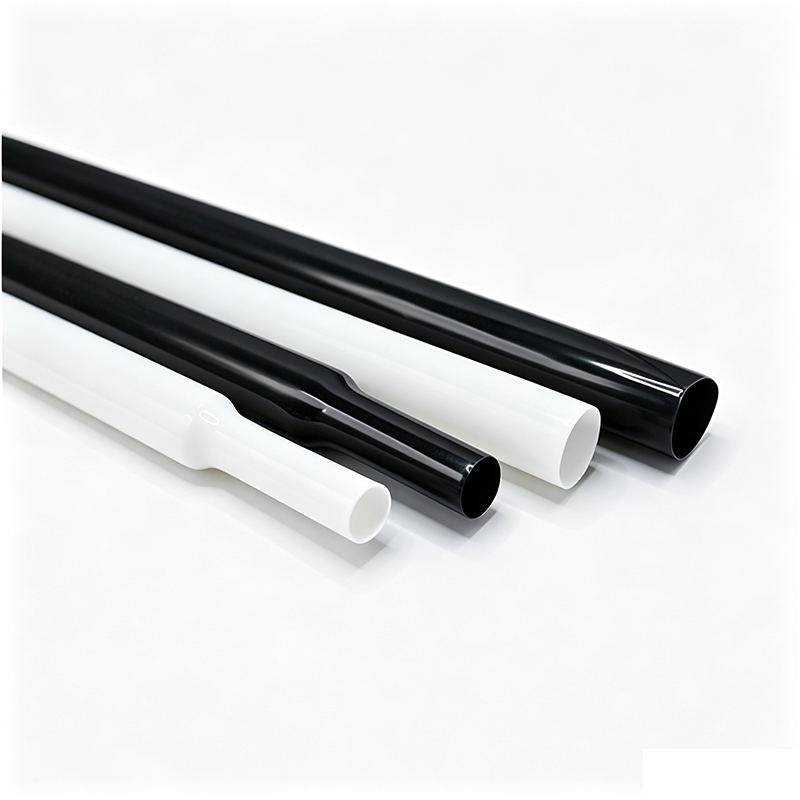
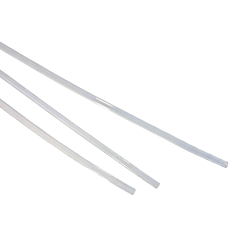
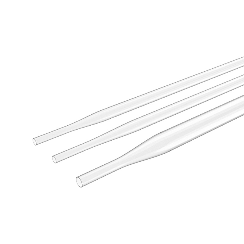
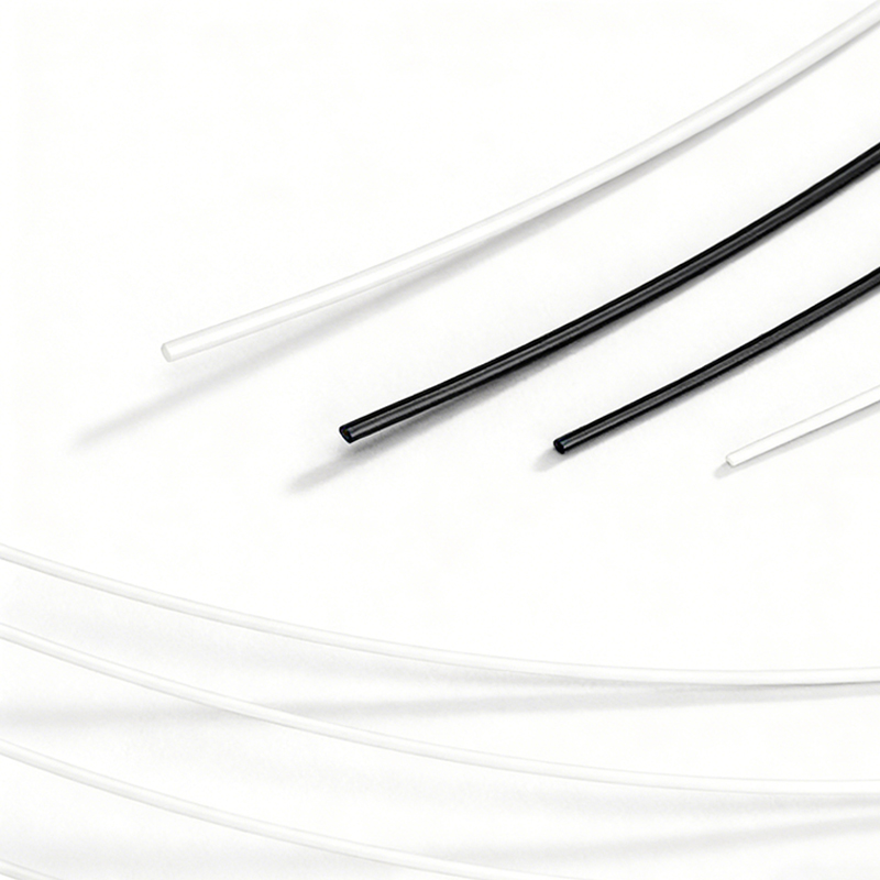
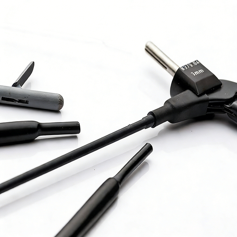
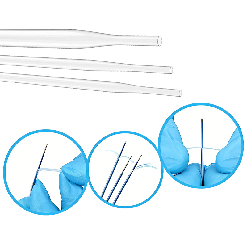
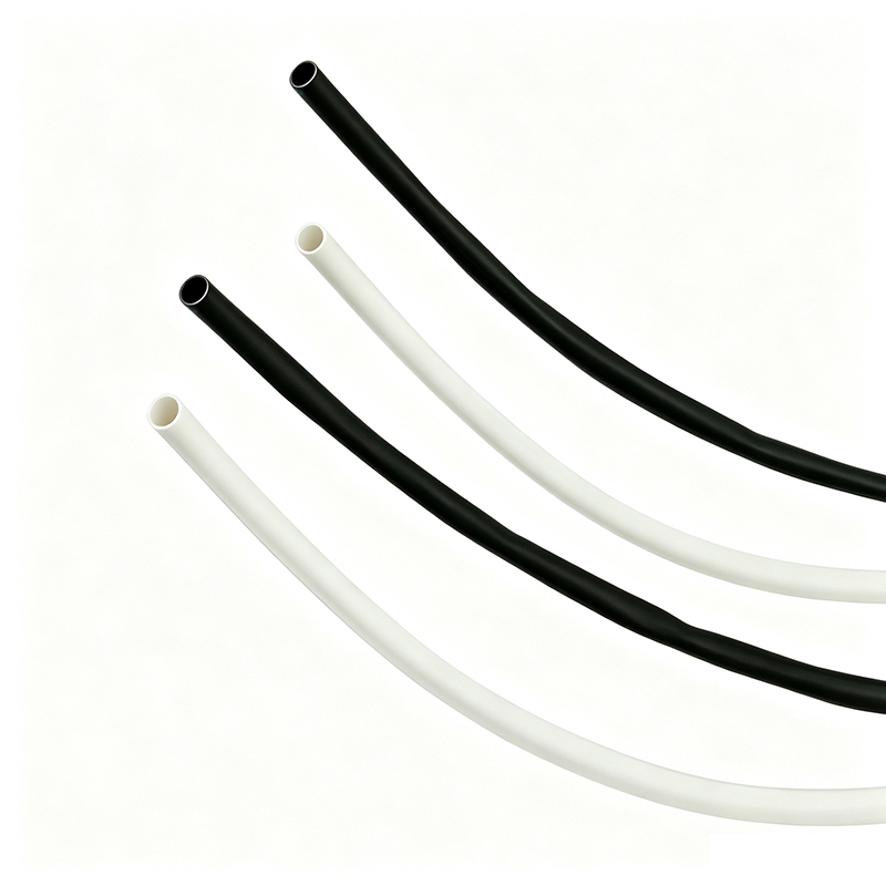
联系我们 No. 77, Bao Nan Road,Nan Lian Community,Long Gang Street,Long Gang District, Shenzhen, Guangdong,518116,China (+86)755 2917 9250 [email protected]BH-MT-PTFE is made of high performance medical grade polytetrafluoroethylene (PTFE) material. PTFE has the best physical properties among plastics, which exhibits the highest performance in electrical property, low friction coefficient, solvent resistance and high temperature resistance. It can provide the most reliable protection for covered medical devices.
Shrink ratio: 1.7:1/4:1
Excellent physical, chemical and electrical performance
Excellent electrical insulation properties
High temperature and abrasion resistance
Compatibility with gamma rays and ETO sterilization
Double plastic bags and plastic spool package
Operating temperature: -65℃~260℃
Minimum fully recovery temperature: 350℃
ISO 10993, USP Class VI compliant
|
Mode l# |
As supplied (mm) |
After fully recovered (mm) |
Standard Length (Meter/Spool) |
||
|
I.D. |
W. T. |
I.D.(max) |
W.T. |
||
|
1.7:1 Shrink ratio (Thick Type) |
|||||
|
BH-MT-PTFE-1.7X-H-0.5 |
0.5±0.2 |
0.15±0.05 |
0.4 |
0.25±0.05 |
200 |
|
BH-MT-PTFE-1.7X-H-1.0 |
1.0±0.2 |
0.15±0.05 |
0.6 |
0.25±0.05 |
200 |
|
BH-MT-PTFE-1.7X-H-1.5 |
1.5±0.2 |
0.20±0.05 |
0.9 |
0.25±0.05 |
200 |
|
BH-MT-PTFE-1.7X-H-2.0 |
2.0±0.2 |
0.20±0.05 |
1.2 |
0.30±0.05 |
200 |
|
BH-MT-PTFE-1.7X-H-2.5 |
2.5±0.3 |
0.20±0.05 |
1.5 |
0.30±0.05 |
200 |
|
BH-MT-PTFE-1.7X-H-3.0 |
3.0±0.3 |
0.20±0.05 |
1.8 |
0.30±0.05 |
200 |
|
BH-MT-PTFE-1.7X-H-3.5 |
3.5±0.3 |
0.20±0.05 |
2.1 |
0.30±0.05 |
200 |
|
BH-MT-PTFE-1.7X-H-4.0 |
4.0±0.3 |
0.20±0.05 |
2.4 |
0.30±0.05 |
100 |
|
BH-MT-PTFE-1.7X-H-4.5 |
4.5±0.3 |
0.20±0.05 |
2.7 |
0.30±0.05 |
100 |
|
BH-MT-PTFE-1.7X-H-5.0 |
5.0±0.3 |
0.20±0.05 |
3.1 |
0.30±0.05 |
100 |
|
BH-MT-PTFE-1.7X-H-5.5 |
5.5+0.5/-0.2 |
0.20±0.05 |
3.3 |
0.30±0.05 |
100 |
|
BH-MT-PTFE-1.7X-H-6.0 |
6.0+0.5/-0.2 |
0.25±0.05 |
3.6 |
0.38±0.05 |
100 |
|
BH-MT-PTFE-1.7X-H-6.5 |
6.5+0.5/-0.2 |
0.25±0.05 |
3.8 |
0.38±0.05 |
100 |
|
BH-MT-PTFE-1.7X-H-7.0 |
7.0+0.5/-0.2 |
0.25±0.05 |
4.2 |
0.38±0.05 |
100 |
|
BH-MT-PTFE-1.7X-H-7.5 |
7.5+0.5/-0.2 |
0.25±0.05 |
4.5 |
0.38±0.05 |
100 |
|
BH-MT-PTFE-1.7X-H-8.0 |
8.0+0.8/-0.2 |
0.25±0.05 |
4.8 |
0.38±0.05 |
100 |
|
BH-MT-PTFE-1.7X-H-8.5 |
8.5+0.8/-0.2 |
0.25±0.05 |
5.0 |
0.38±0.05 |
100 |
|
BH-MT-PTFE-1.7X-H-9.0 |
9.0+0.8/-0.2 |
0.25±0.05 |
5.3 |
0.38±0.05 |
100 |
|
BH-MT-PTFE-1.7X-H-9.5 |
9.5+0.8/-0.2 |
0.25±0.05 |
5.6 |
0.38±0.05 |
100 |
|
BH-MT-PTFE-1.7X-H-10.0 |
10+0.8/-0.2 |
0.25±0.05 |
5.9 |
0.38±0.05 |
100 |
|
1.7:1 Shrink ratio (Thin Type) |
|||||
|
BH-MT-PTFE-1.7X-B-0.5 |
0.5±0.2 |
0.10±0.05 |
0.4 |
0.15±0.05 |
200 |
|
BH-MT-PTFE-T1.7X-B-1.0 |
1.0±0.2 |
0.10±0.05 |
0.6 |
0.15±0.05 |
200 |
|
BH-MT-PTFE-1.7X-B-1.5 |
1.5±0.2 |
0.10±0.05 |
0.9 |
0.15±0.05 |
200 |
|
BH-MT-PTFE-1.7X-B-2.0 |
2.0±0.2 |
0.10±0.05 |
1.2 |
0.15±0.05 |
200 |
|
BH-MT-PTFE-1.7X-B-2.5 |
2.5±0.3 |
0.10±0.05 |
1.5 |
0.15±0.05 |
200 |
|
BH-MT-PTFE-1.7X-B-3.0 |
3.0±0.3 |
0.15±0.05 |
1.8 |
0.20±0.05 |
200 |
|
BH-MT-PTFE-1.7X-B-3.5 |
3.5±0.3 |
0.15±0.05 |
2.1 |
0.20±0.05 |
200 |
|
BH-MT-PTFE-1.7X-B-4.0 |
4.0±0.3 |
0.15±0.05 |
2.4 |
0.20±0.05 |
100 |
|
BH-MT-PTFE-1.7X-B-4.5 |
4.5±0.3 |
0.15±0.05 |
2.7 |
0.20±0.05 |
100 |
|
BH-MT-PTFE-1.7X-B-5.0 |
5.0±0.3 |
0.15±0.05 |
3.1 |
0.20±0.05 |
100 |
|
BH-MT-PTFE-1.7X-B-5.5 |
5.5+0.5/-0.2 |
0.15±0.05 |
3.3 |
0.20±0.05 |
100 |
|
BH-MT-PTFE-T1.7X-B-6.0 |
6.0+0.5/-0.2 |
0.15±0.05 |
3.6 |
0.25±0.05 |
100 |
|
BH-MT-PTFE-1.7X-B-6.5 |
6.5+0.5/-0.2 |
0.15±0.05 |
3.8 |
0.25±0.05 |
100 |
|
BH-MT-PTFE-1.7X-B-7.0 |
7.0+0.5/-0.2 |
0.18±0.05 |
4.2 |
0.25±0.05 |
100 |
|
BH-MT-PTFE-T1.7X-B-7.5 |
7.5+0.5/-0.2 |
0.18±0.05 |
4.5 |
0.25±0.05 |
100 |
|
BH-MT-PTFE-1.7X-B-8.0 |
8.0+0.8/-0.2 |
0.18±0.05 |
4.8 |
0.25±0.05 |
100 |
|
BH-MT-PTFE-1.7X-B-8.5 |
8.5+0.8/-0.2 |
0.18±0.05 |
5.0 |
0.25±0.05 |
100 |
|
BH-MT-PTFE-1.7X-B-9.0 |
9.0+0.8/-0.2 |
0.18±0.05 |
5.3 |
0.25±0.05 |
100 |
|
BH-MT-PTFE-1.7X-B-9.5 |
9.5+0.8/-0.2 |
0.18±0.05 |
5.6 |
0.25±0.05 |
100 |
|
BH-MT-PTFE-1.7X-B-10.0 |
10+0.8/-0.2 |
0.20±0.05 |
5.9 |
0.25±0.05 |
100 |
|
4:1 Shrink ratio |
|||||
|
BH-MT-PTFE-4X-2.5 |
2.5+0.5/-0.2 |
0.10±0.05 |
0.62 |
0.25±0.05 |
200 |
|
BH-MT-PTFE-4X-3.0 |
3.0+0.5/-0.2 |
0.10±0.05 |
0.75 |
0.25±0.05 |
200 |
|
BH-MT-PTFE-4X-3.5 |
3.5+0.5/-0.2 |
0.10±0.05 |
0.87 |
0.30±0.05 |
200 |
|
BH-MT-PTFE-4X-4.0 |
4.0+0.5/-0.2 |
0.10±0.05 |
1.00 |
0.30±0.05 |
100 |
|
BH-MT-PTFE-4X-4.5 |
4.5+0.5/-0.2 |
0.10±0.05 |
1.12 |
0.30±0.05 |
100 |
|
BH-MT-PTFE-4X-5.0 |
5.0+0.8/-0.2 |
0.10±0.05 |
1.25 |
0.30±0.05 |
100 |
|
BH-MT-PTFE-4X-6.0 |
6.0+0.8/-0.2 |
0.10±0.05 |
1.50 |
0.30±0.05 |
100 |
|
BH-MT-PTFE-4X-7.0 |
7.0+0.8/-0.2 |
0.10±0.05 |
1.75 |
0.30±0.05 |
100 |
|
BH-MT-PTFE-4X-8.0 |
8.0+1.0/-0.2 |
0.10±0.05 |
2.00 |
0.30±0.05 |
100 |
|
BH-MT-PTFE-4X-9.0 |
9.0+1.0/-0.2 |
0.10±0.05 |
2.25 |
0.30±0.05 |
100 |
|
BH-MT-PTFE-4X-10.0 |
10+1.0/-0.5 |
0.10±0.05 |
2.50 |
0.30±0.05 |
100 |
|
BH-MT-PTFE-4X-11.0 |
11+1.0/-0.5 |
0.10±0.05 |
2.75 |
0.30±0.05 |
100 |
|
BH-MT-PTFE-4X-12.0 |
12+1.0/-0.5 |
0.10±0.05 |
3.00 |
0.30±0.05 |
100 |
Customized dimensions are available on request for your special application.
|
Property |
Specification Requirement |
Test Method |
Typical Value |
|
Tensile strength |
≥17.3MPa |
ASTM D2671 |
≥22MPa |
|
Elongation at break |
≥200% |
ASTM D2671 |
≥300% |
|
Heat shock |
No cracking |
ASTM D2671 |
No cracking |
|
Low temperature flexibility |
No cracking |
ASTM D2671 |
No cracking |
|
Volume resistivity |
≥1015Ω‧ cm |
ASTM D2671 |
≥1015Ω‧ cm |
|
Dielectric strength |
≥34kV/mm |
ASTM D2671 |
34 kV/mm |
|
Copper corrosion |
No corrosion |
ASTM D2671 |
No corrosion |
|
No heavy metals contained |
|||
Written for catheter and electrosurgical-device R&D and process engineers, OEM/ODM partners and sourcing teams. This FAQ focuses on selection, PTFE-specific thermal processing, failure modes, sterilization, compliance boundaries and sourcing practice. All physical properties, dimensions, shrink ratios and test values are published in the product datasheet and are intentionally not repeated here — refer to the BH-MT-PTFE product page for the full specification.
Q1. What should we verify before selecting BH-MT-PTFE for a medical device build?
A1. Four checkpoints.
(1) Dimensional fit: the as-supplied ID must slide over your component, and the recovered ID and recovered wall must deliver the radial compression your design needs — cross-check the tolerance bands against our datasheet rather than assuming equivalence with another supplier’s PTFE sleeve.
(2) Processing prerequisites: PTFE recovers at substantially higher temperatures than polyolefin or PVDF heat shrink (see datasheet); confirm that your line has controlled high-temperature heating equipment and that everything under the sleeve tolerates the recovery step.
(3) Shrink-ratio family: a standard-ratio family (thick-wall and thin-wall versions) and a high-ratio family are offered — choose based on the ratio between the largest and smallest diameter you need to cover.
(4) Complete your own process validation (IQ/OQ/PQ) before production release; evaluation samples are available for exactly this purpose.
Q2. Which heating equipment is suitable for recovering PTFE heat shrink, and what failure modes should we watch for?
A2. PTFE’s recovery window sits far above what ordinary bench heat guns deliver uniformly (see datasheet for the recovery temperature). In practice, engineers use calibrated forced-air convection ovens, infrared heating tunnels, or heated-mandrel stations with closed-loop temperature control; an uncontrolled flame or consumer-grade heat gun creates local hot spots and uneven recovery. Failure modes frequently reported with PTFE sleeves:
(1) bubbles or blisters — PTFE itself is not hygroscopic, so bubbles usually trace to air sealed in at the ends, outgassing from the substrate or mandrel, or heating that is too rapid;
(2) whitening or chalky marks — stress whitening from kinking, tight bending or mechanical abuse during handling; light uniform whitening is usually cosmetic, but whitening combined with surface crazing after heating can indicate over-stressing and should be checked by cross-section;
(3) crushing or imprinting of fragile substrates — PTFE develops high recovery force, and over thin-wall polymer tubes or soft components it can reduce lumen diameter or mark the surface, so qualify the compression on your real build;
(4) longitudinal shrink shift — PTFE recovers axially as well as radially, so position the sleeve with allowance and heat symmetrically from the center outward to avoid drift, end exposure or splitting.
Q3. What should we know about contact with PEBAX, PFA, FEP, metals and medical adhesives?
A3. Two mechanisms matter: temperature and adhesion. On temperature: the recovery heat of a PTFE sleeve is above the melt range of PEBAX, Nylon and PU jackets, so do not recover it directly over these substrates unless the assembly is supported and the heat exposure is proven harmless — for low-temperature jacket reflow work, choose a lower-temperature process-aid sleeve from our range instead. PTFE over metals (stainless hypotubes, guidewires, electrosurgical shafts, leads and coils) is the classic fit. PFA and FEP components tolerate elevated temperatures, but validate the exact stack because the PTFE recovery step reaches deep into their service range. On adhesion: PTFE is chemically inert and non-stick — medical adhesives, primers and potting compounds do not bond to it without surface treatment (such as sodium etching or plasma treatment). If your design requires bonding to or over the sleeve, plan that step explicitly or contact us to discuss options.
Q4. Any precautions for chemicals and disinfectants, and what material declarations are available?
A4. PTFE is among the most chemically resistant polymers in use: it is essentially unaffected by common hospital disinfectants, alcohols and most solvents, which is a key reason it is selected for harsh reprocessing environments. If your device will see repeated wipe-downs or immersion in a specific agent, share the chemistry and exposure cycle with us and we will support a compatibility assessment. On documentation: the material contains no heavy metals (see datasheet), and we support your material-declaration work with composition statements and ISO 10993 / USP Class VI material test reports. Note that fluoropolymers are receiving increased regulatory attention in some regions; if your market-access team needs substance-level declarations (for example for EU MDR 10.4 screening or PFAS-related customer questionnaires), raise this in the RFQ so the correct documentation is prepared from the start.
Q5. How do steam autoclaving, gamma and EtO affect the tubing — and what about repeated cycles?
A5. The datasheet qualifies the tubing for gamma irradiation and EtO sterilization. Two honest boundary notes.
(1) Steam autoclaving is not listed as a qualified method for this product. The PTFE polymer family physically tolerates autoclave temperatures, but engineers frequently report that on recovered thin-wall sleeves, repeated pre-vacuum steam cycles drive shrink-back at the sleeve ends, moisture entrapment and blistering between sleeve and metal substrate, and creep at bend points — because the sleeve grips the substrate mechanically, not chemically. If your device requires steam reprocessing, treat it as a formal validation item and request samples for cycle testing.
(2) Repeated sterilization of any kind should be validated on the recovered sleeve on your actual device: verify dimensional stability, surface condition and dielectric performance after the full intended number of cycles.
Q6. Where is PTFE heat shrink the right choice — and where is it NOT recommended?
A6. Well suited: electrical insulation of electrosurgical instrument shafts, leads and connections; protection of metal components, guidewires and probes; high-temperature and chemically aggressive environments; low-friction covering of shafts and instruments; process use where the substrate tolerates the recovery heat. Use with caution or not recommended: joints under continuous dynamic flexing — PTFE is stiffer than FEP/PFA and more prone to fatigue and stress whitening at tight, repeated bend radii; high-abrasion sliding contact, where FEP or PFA sleeves generally wear better; and recovery directly over low-melting thermoplastic jackets (see the compatibility question). If your application is dominated by repeated bending or abrasion, tell us — an FEP/PFA-based solution or a different wall-thickness version may be the better engineering choice, and we would rather tell you that before your design freeze than after.
Q7. Does ISO 10993 / USP Class VI compliance — or the published dielectric rating — mean our finished device is approved?
A7. No — and this distinction matters in audits. We supply component tubing only. Material-level compliance with ISO 10993 / USP Class VI supports, but does not replace or constitute, regulatory approval of your finished medical device: biological evaluation of the finished device (ISO 10993-1), sterilization validation, process validation (IQ/OQ/PQ) and risk analysis (ISO 14971) remain the device manufacturer’s responsibility. The same logic applies electrically: the dielectric properties published in our datasheet are material-level test values, not an electrical safety certification of your instrument. Dielectric withstand (hi-pot), leakage current, creepage and clearance verification on the finished device (for example under the IEC 60601 series where applicable) must be performed and documented by you on the final assembly, including after sterilization and aging. We do not claim performance beyond the published datasheet.
Q8. How should the tubing be stored, and does long-term storage change its properties?
A8. PTFE is one of the most aging-resistant polymers available: it contains no plasticizers that could migrate, does not absorb moisture, and is stable against UV and oxidation, so the material itself has no practical shelf-life driver — the datasheet does not assign a fixed shelf life. Practical guidance: keep the spools in their packaging, stored clean, dry and away from direct heat sources; avoid crushing, kinking or sharply bending the tubing during storage and handling, because mechanical deformation before recovery can leave whitening marks and cause uneven recovery; apply first-in-first-out rotation. For lots stored for an extended period, run a quick recovery check on a sample piece before releasing the lot to production, and include storage conditions in your incoming-inspection plan.
Q9. Do you support cutting, hole punching, custom dimensions or special shrink ratios?
A9. Cut-to-length supply is supported and is the most common secondary operation for this product. Customized dimensions are available on request for special applications (see datasheet), and special shrink-ratio or wall-thickness requirements can be evaluated case by case. For operations such as hole punching or laser marking: PTFE can be machined and punched, but any feature cut into the sleeve changes its local recovery behavior (stress concentration, split initiation at the feature edge), so we evaluate such requests together with your process team before committing. Describe the requirement in your RFQ and we will confirm feasibility and achievable tolerances.
Q10. How do samples and the ramp from trials to mass production work?
A10. Evaluation samples of standard sizes are available so you can qualify the recovery window on your real equipment and substrate — this is exactly what they are for, because PTFE recovery is equipment-sensitive and we recommend finalizing your heating recipe with sample material before freezing the design. After successful trials we support pilot batches and then ramp to mass production, with lead times confirmed at quotation. If you are dual-sourcing against an incumbent fluoropolymer supplier, give us the reference specification and we will map the closest equivalent for side-by-side trials.
Q11. What engineering information should an RFQ include?
A11. To receive a fast and accurate quotation, please provide: required size (as-supplied ID and/or recovered ID, plus any wall-thickness requirement); shrink-ratio family (standard or high-ratio) based on your diameter transition; quantity and estimated annual volume; supply form (spool or cut length, with tolerance and edge-quality requirement); the application and what sits under the sleeve (metal shaft, wire, polymer tube — with material and any size-critical lumen); your heating equipment type and available process temperature; sterilization method and the number of cycles the device must survive; electrical requirements if used as insulation (operating voltage and the hi-pot test level of the finished device); secondary operations (cutting, holes, marking); compliance documentation required (ISO 10993 / USP Class VI material reports, composition and heavy-metal declarations); and target price, delivery terms and destination.
12. Material Declaration & Master Files
Q12. What should we know about material declarations, MDM documentation and FDA master files?
A12. Practical points.
(1) We provide material-level documentation — composition statement, no-heavy-metals statement (see datasheet) and ISO 10993 / USP Class VI material test reports — for your technical file, EU MDR documentation or supplier-qualification records.
(2) Where a device master file (MAF) reference is the right mechanism, we can discuss authorization letters so your regulatory team can reference our material data in your submission; the scope is agreed case by case.
(3) What we do not do: we make no claim or commitment on behalf of your finished device — our material documents imply no device-level FDA clearance, no CE conformity, and no device-level biological or electrical safety approval.
(4) Change control: if your regulatory filing requires notification agreements for material or process changes, raise this before design freeze so it is covered in the supply agreement.