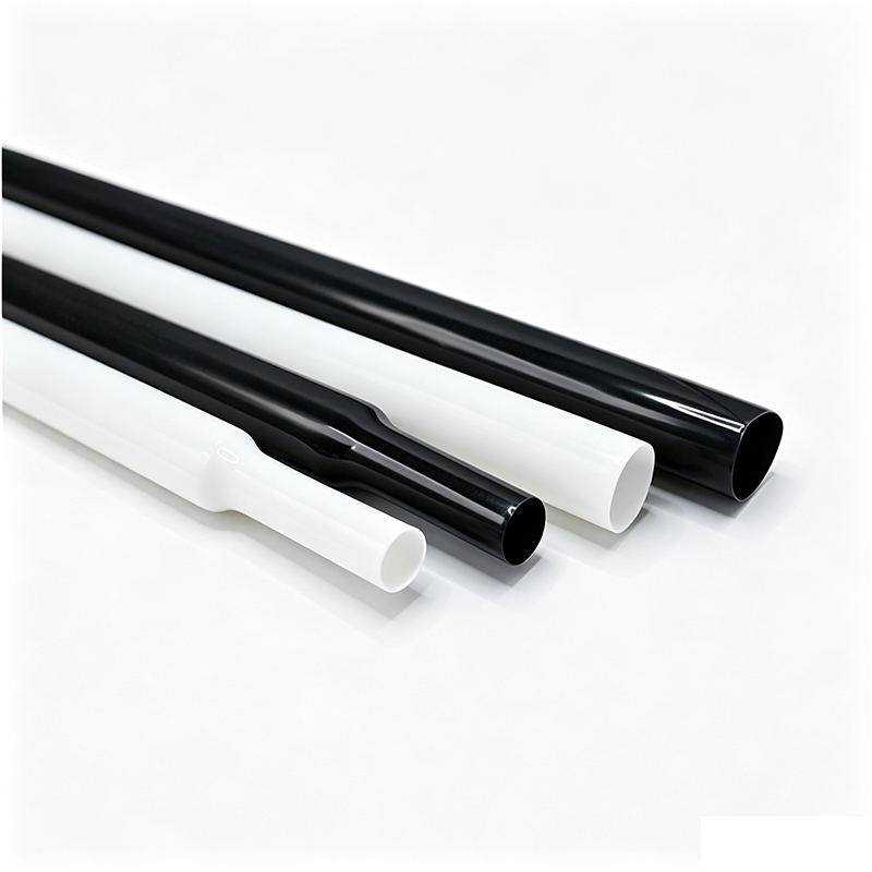
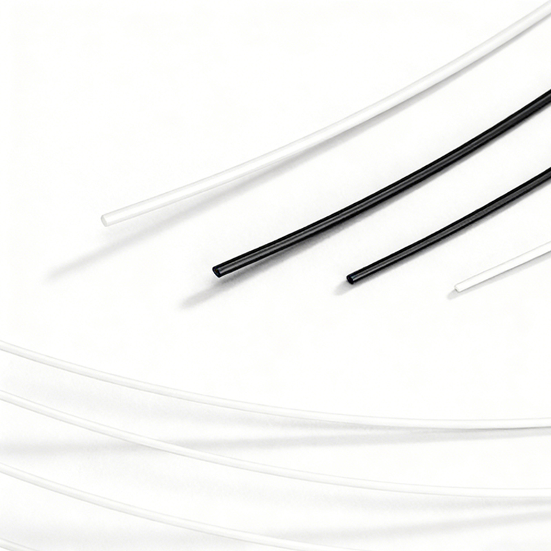
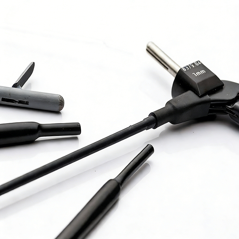
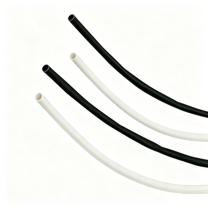
|
Model
|
Expanded ID
(Min.) (mm)
|
Fully recovered
ID (Max.)(mm)
|
Fully recovered
W.T. (mm)
|
Standard Length
(mm)
|
|
1.3:1
|
1.6:1
|
|
BH-MT-FEP-0.64
|
0.64
|
0.50
|
0.40
|
0.20±0.05
|
1220±10
|
|
BH-MT-FEP-0.80
|
0.80
|
0.61
|
0.50
|
0.20±0.05
|
1220±10
|
|
BH-MT-FEP-0.96
|
0.96
|
0.74
|
0.60
|
0.20±0.05
|
1220±10
|
|
BH-MT-FEP-1.1
|
1.10
|
0.85
|
0.70
|
0.20±0.05
|
1220±10
|
|
BH-MT-FEP-1.6
|
1.60
|
1.24
|
1.00
|
0.25±0.05
|
1220±10
|
|
BH-MT-FEP-2.0
|
2.00
|
1.54
|
1.25
|
0.25±0.05
|
1220±10
|
|
BH-MT-FEP-2.5
|
2.50
|
1.93
|
1.57
|
0.25±0.05
|
1220±10
|
|
BH-MT-FEP-3.0
|
3.00
|
2.30
|
1.88
|
0.25±0.05
|
1220±10
|
|
BH-MT-FEP-3.5
|
3.50
|
2.70
|
2.19
|
0.25±0.05
|
1220±10
|
|
BH-MT-FEP-4.0
|
4.00
|
3.08
|
2.50
|
0.25±0.05
|
1220±10
|
|
BH-MT-FEP-4.5
|
4.50
|
3.62
|
2.81
|
0.25±0.05
|
1220±10
|
|
BH-MT-FEP-5.0
|
5.00
|
3.85
|
3.12
|
0.25±0.05
|
1220±10
|
|
BH-MT-FEP-6.0
|
6.00
|
4.62
|
3.75
|
0.35±0.05
|
1220±10
|
|
BH-MT-FEP-7.0
|
7.00
|
5.4
|
4.38
|
0.35±0.05
|
1220±10
|
|
BH-MT-FEP-8.0
|
8.00
|
6.16
|
5.00
|
0.35±0.05
|
1220±10
|
|
BH-MT-FEP-9.0
|
9.00
|
6.93
|
5.63
|
0.35±0.05
|
1220±10
|
|
BH-MT-FEP-10.0
|
10.00
|
7.7
|
6.25
|
0.35±0.05
|
1220±10
|
|
BH-MT-FEP-11.0
|
11.00
|
8.47
|
6.88
|
0.35±0.05
|
1220±10
|
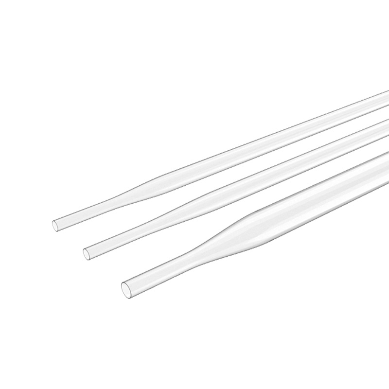
Customized dimensions and heat shrink ratio for your special applications on request.
|
Property
|
Test Method
|
Typical Data
|
|
Longitudinal change/%
|
ASTM D 2671
|
±10
|
|
Tensile strength/MPa
|
ASTM D 638
|
≥13.8
|
|
Elongation at break/%
|
ASTM D 638
|
≥200
|
|
Low temperature flexibility
|
AMS-DTL-23053 (-65°C, 4h)
|
No cracks
|
|
Dielectric strength/kV/mm
|
ASTM D 2671
|
≥19.7
|
|
Voltage withstand
|
ASTM D 149
|
4000V, 60s No breakdown
|
Q1. After reflow, the FEP shrink sleeve will not come off cleanly — it breaks into fragments or leaves residue, and operators end up picking at it with blades. How can I remove it without leaving residue on the shaft?
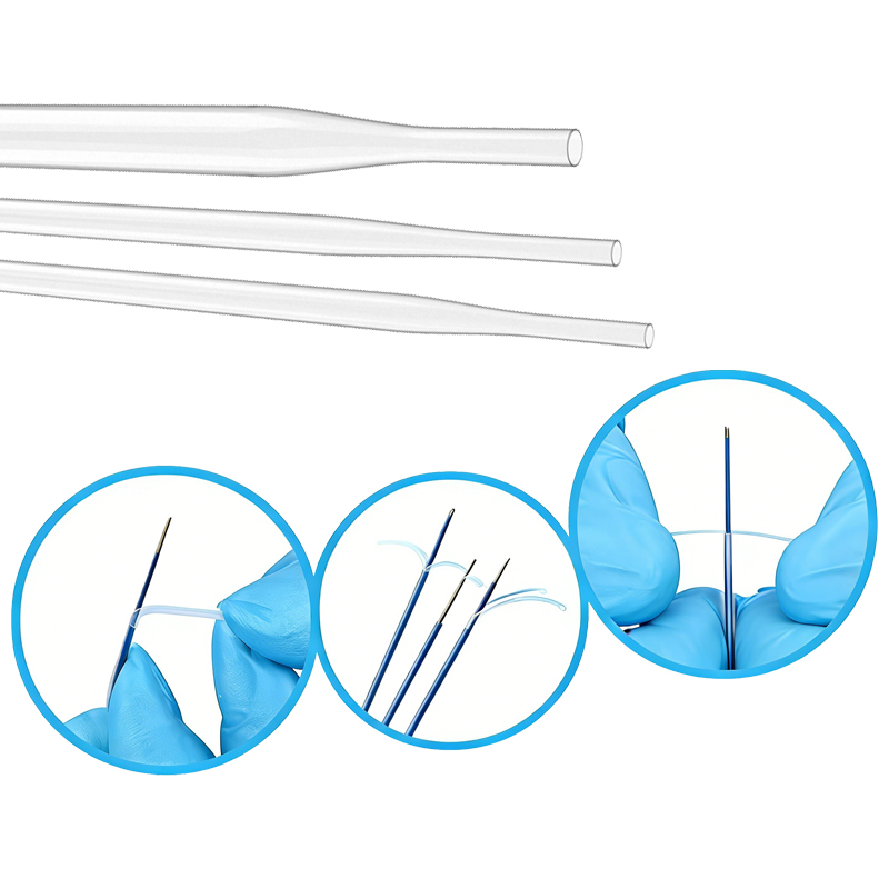
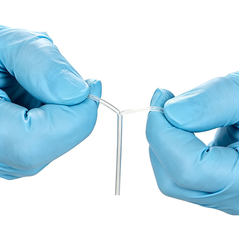
A1. FEP is inherently non-stick, so true “residue” is rarely the polymer itself. In practice, fragments and residue usually come from three sources: blade skiving that chops the sleeve into shards; silicone-based processing aids used in some low-grade tubing that transfer to the jacket; and peeling while the assembly is still warm, when the sleeve is soft and tears instead of peeling. Recommended practice: allow the assembly to cool fully to near ambient before removal; make one shallow axial score or slit at the peel start (deep scoring cuts into the jacket underneath); peel at a low angle with a steady axial pull; specify silicone-free tubing with consistent wall thickness. BH-MT-FEP is supplied as a temporary process sleeve engineered for clean release after reflow; material certificates and inspection reports are available on request for your own evaluation.
Q2. When we remove the heat shrink after reflow, we keep scratching or gouging the soft Pebax (25D–45D) and TPU outer jackets — and sometimes the damage only appears at final inspection. How do we protect these soft jackets?
A2. The dominant cause is razor skiving of a non-peelable sleeve near a soft, low-durometer jacket: one slip and the blade tracks along the shaft, and the scratch may be shallow enough to survive until final visual inspection. The fix is to change the removal method, not to ask operators to be more careful. Replace blade skiving with score-and-peel removal wherever possible; support the shaft in a soft V-block or fixture during peeling to avoid bending stress on the freshly laminated section; keep the peel angle low and the pull axial — twisting or radial prying marks soft jackets. BH-MT-FEP’s clarity also allows jacket condition to be checked under magnification immediately after reflow, instead of discovering damage at final inspection — one of the main reasons engineers choose FEP over opaque PTFE sleeves for soft-jacket constructions.
Q3. After jacket lamination over the braid we see unbonded spots, voids and OD variation along the shaft — the radial pressure from the shrink sleeve seems uneven. What causes this, and how do we fix it?
A3. Uneven consolidation is a pressure problem, a thermal problem, or both. Typical root causes: expanded ID too large relative to the assembly (a loose sleeve cannot generate enough radial pressure to drive the molten jacket into the braid interstices); inconsistent wall thickness or pre-expansion tolerance of the sleeve (thick and thin zones shrink with different force, producing OD bands along the shaft); insufficient reflow temperature or dwell (the jacket never fully melts and wets the etched liner); thermal gradients in the oven and braid-density changes along the shaft. Recommended practice: select a recovered ID close to the target finished OD; choose the shrink ratio to match the profile (see Q6); and require tight control of expanded-ID and wall tolerance from your tubing supplier so every lot behaves identically in a validated process. BH-MT-FEP is dimensionally inspected with pre-expansion tolerance control for exactly this reason.
Q4. We cannot see what is happening during reflow or balloon forming with our current sleeve, and defects are only found after removal. Is there a way to inspect the assembly during and right after the thermal cycle?
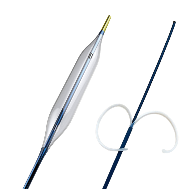
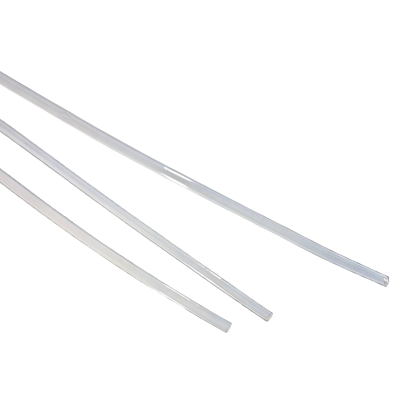
A4. Yes — this is a material-selection issue. PTFE-based sleeves are opaque; FEP is naturally highly transparent even at thin walls, which is why it is the default choice where in-process visibility matters. With a clear BH-MT-FEP sleeve you can directly observe: jacket melt and flow over the braid (voids and unmelted zones); marker-band position and braid shift; balloon cone formation and wall uniformity during forming; surface finish of the recovered shaft before the sleeve is peeled. In-process visibility converts end-of-line surprises into immediate corrections and is one of the cheapest scrap-reduction measures on a reflow line.
Q5. What cooling method should we use after reflow? Does the water bath temperature actually matter, and could removing the sleeve while it is still warm cause it to stick or smear onto the Pebax / TPU jacket?
A5. Cooling is part of the process, not an afterthought. An uncontrolled or uneven quench freezes residual stress into the shaft, causes ovality and can open up layer interfaces that were still molten. A common setup is a uniform water quench at roughly ambient to about 40 °C (customer to validate for their construction), with agitation or movement through the bath to avoid thermal gradients along a long shaft. On removal temperature: yes — removing the sleeve while it is still warm is a classic cause of smearing and sticking. A warm FEP sleeve is soft and compliant, so it can adhere locally to the still-tacky jacket surface, stretch rather than release, and leave glossy smear marks that fail cosmetic inspection; over-chilling a thin-wall shaft can instead make the assembly brittle and prone to kinking. Recommended practice: quench uniformly, let the assembly stabilize to near ambient, then score and peel.
Q6. How do I select the shrink ratio (1.3:1 vs 1.6:1 vs 2:1), and what tolerance should I require on the expanded ID?
A6. The shrink ratio is chosen from geometry, not from habit. Measure the largest outside feature the sleeve must slide over (braid bumps, marker bands, flared transitions, the balloon cone area) and the smallest finished dimension it must recover onto; the ratio must cover that diameter range with enough margin for easy loading but not so much margin that the sleeve sits loose where pressure matters. Rule of thumb: near-uniform shafts and single-diameter reflow → 1.3:1 (tightest, most pressure-consistent fit); stepped or tapered shafts and distal transitions → 1.6:1; large diameter jumps, flare forming or aggressive tapers → 2:1, recovering across a wide range in a single cycle. On expanded-ID tolerance: this is the most often underestimated parameter. The expanded ID sets both loading clearance and recovered pressure; a loose tolerance lets recovered force and final OD drift from lot to lot, showing up directly as the OD banding and voids in Q3. Require a tight expanded-ID and wall-thickness tolerance, and confirm longitudinal shrinkage is controlled (typically within about ±5%). BH-MT-FEP is supplied with dimensional inspection data on request so each lot can be qualified against your validated process window.